
We have compiled a practical after-sales service guide: three ways to connect the host software (PC), parameter descriptions, wiring definitions, and common faults with their solutions. With clear illustrations and step-by-step instructions, we recommend saving this article for future reference — pull it up anytime you run into an issue on site.
PART 01
How to Connect the Host Software
There are three ways to connect the host software (PC) to the laser: serial port, Ethernet cable, and mobile hotspot.
▍ Method 1: Serial Port Connection
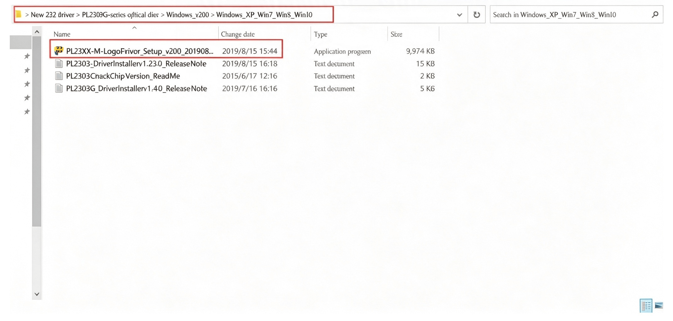
Step 1: Install the RS232 serial cable driver.
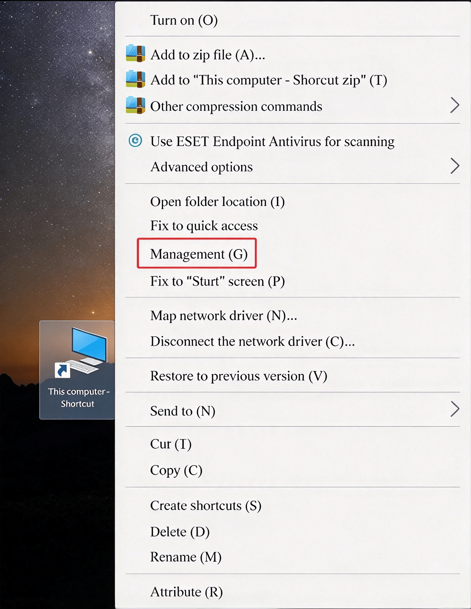
Step 2: Find the COM port number of the RS232 cable on your PC. Right-click "This PC" and select "Manage".
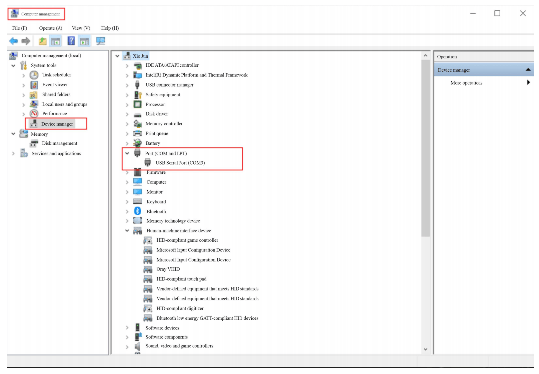
Step 3: Open the Device Manager and expand the Ports section. Confirm the RS232 port number — in the example shown, the port is "COM3".
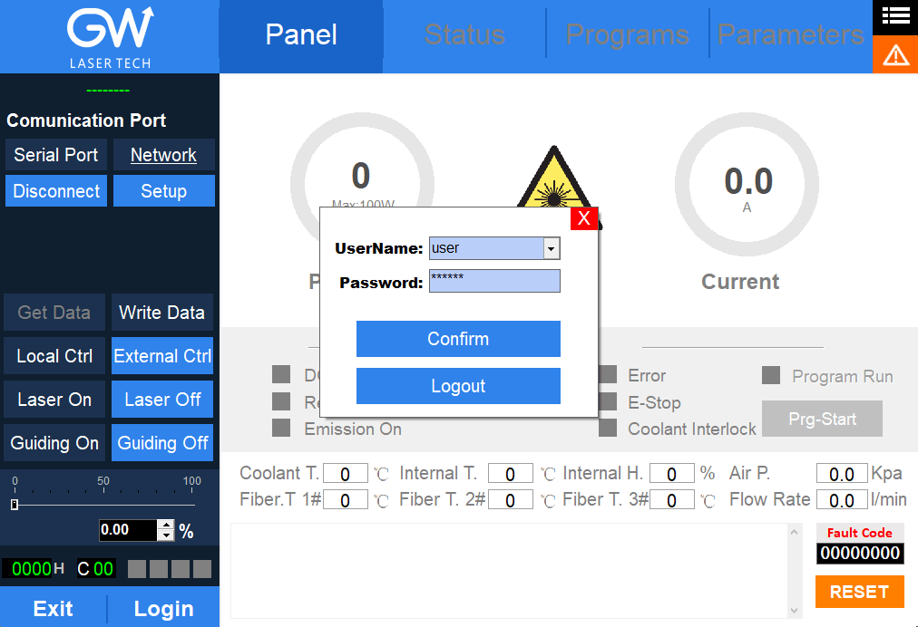
Step 4: Open the host software, click Login, and enter the password 000000.
Step 5: Click "Serial Port", then click "Settings".
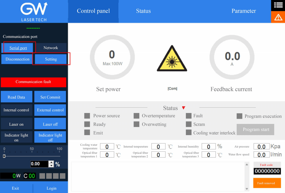
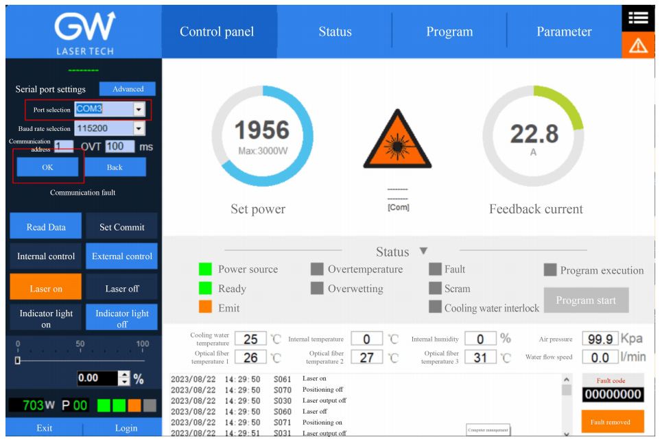
Step 6: Select the port number and click "OK".
▍ Method 2: Ethernet Cable Connection
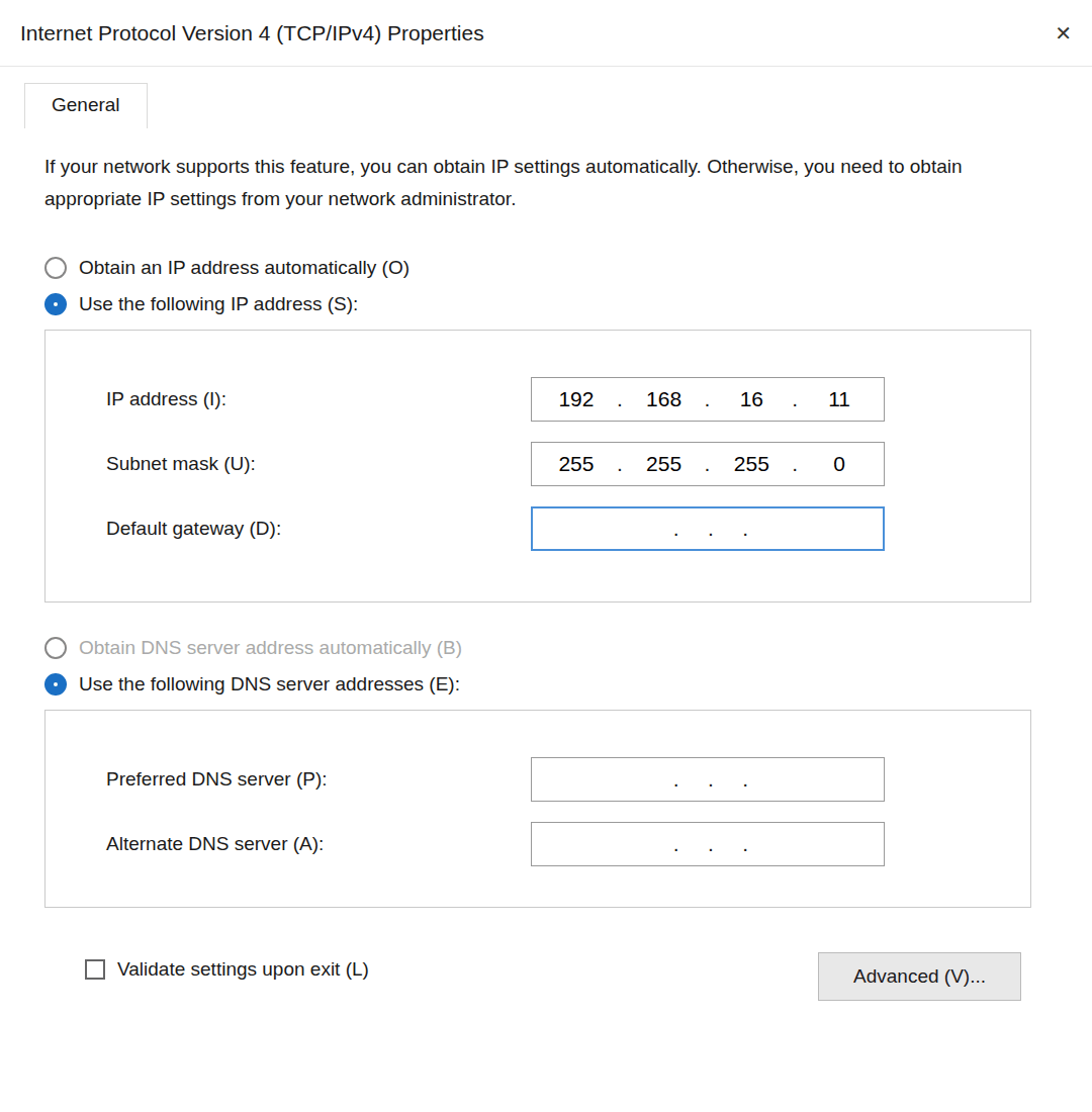
Step 1: Modify the IP address of your computer.
Step 2: Open the host software. After logging in, click "Network", then click "Settings".
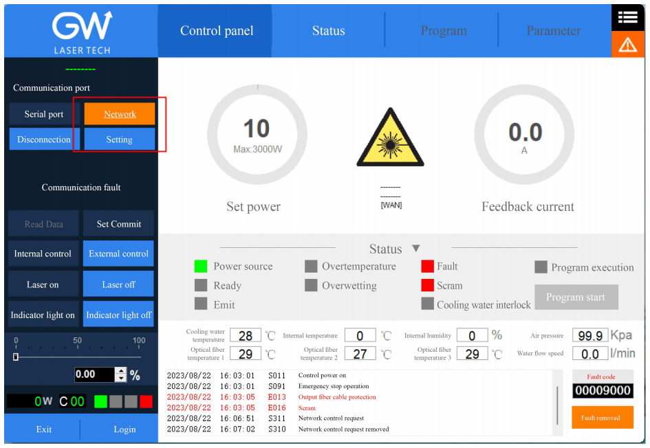
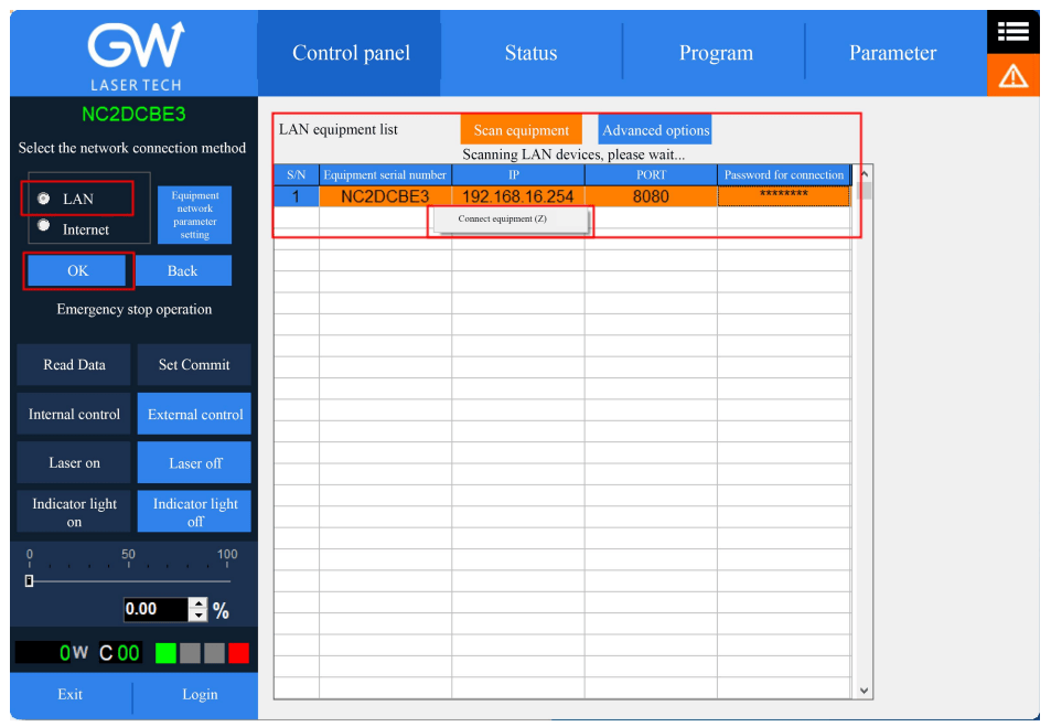
Step 3: Select the LAN, click "OK", then click "Scan Devices". Select the device serial number, right-click and choose "Connect Device".
▍ Method 3: Hotspot Connection
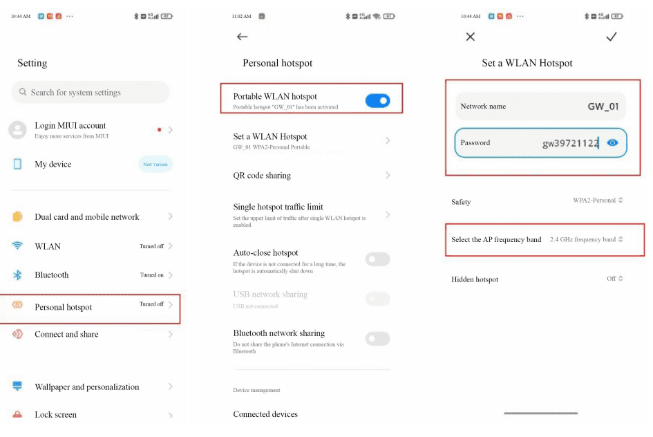
Android phones: Enable Personal Hotspot → Portable WLAN Hotspot → set Network Name to GW_01 → set Password to gw39721122 → set AP Band to 2.4GHz.
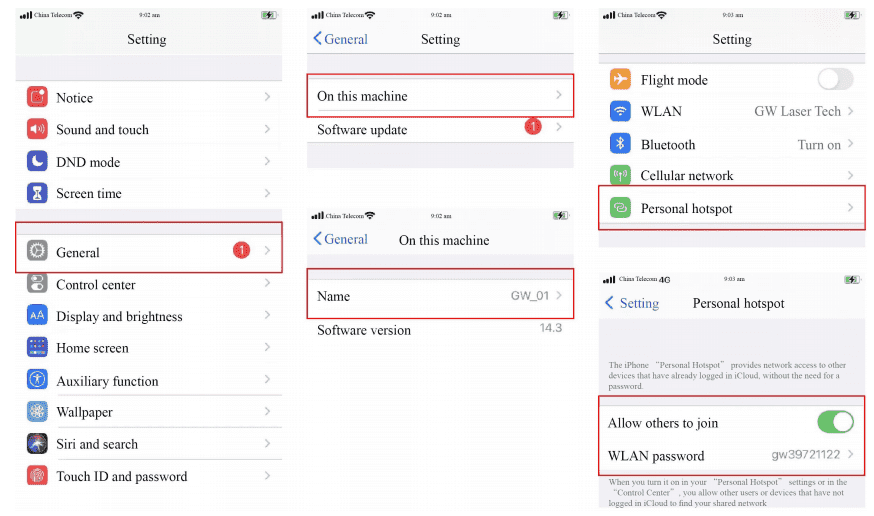
iPhones: Go to Settings → General → About and change the device Name to GW_01. Then go back to Settings → Personal Hotspot → enable Allow Others to Join → change the Wi-Fi Password to gw39721122.
PART 02
Host Software Interface & Parameter Settings
▍ Interface Overview
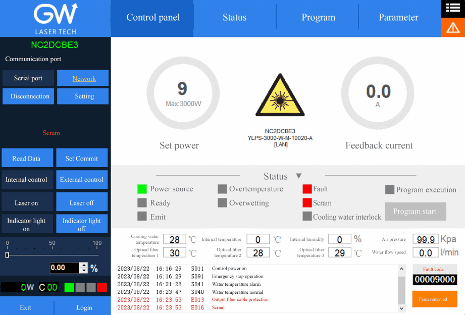
The host software interface consists of four main modules: Control Panel, Status, Program, and Parameters.
▍ Parameter Settings
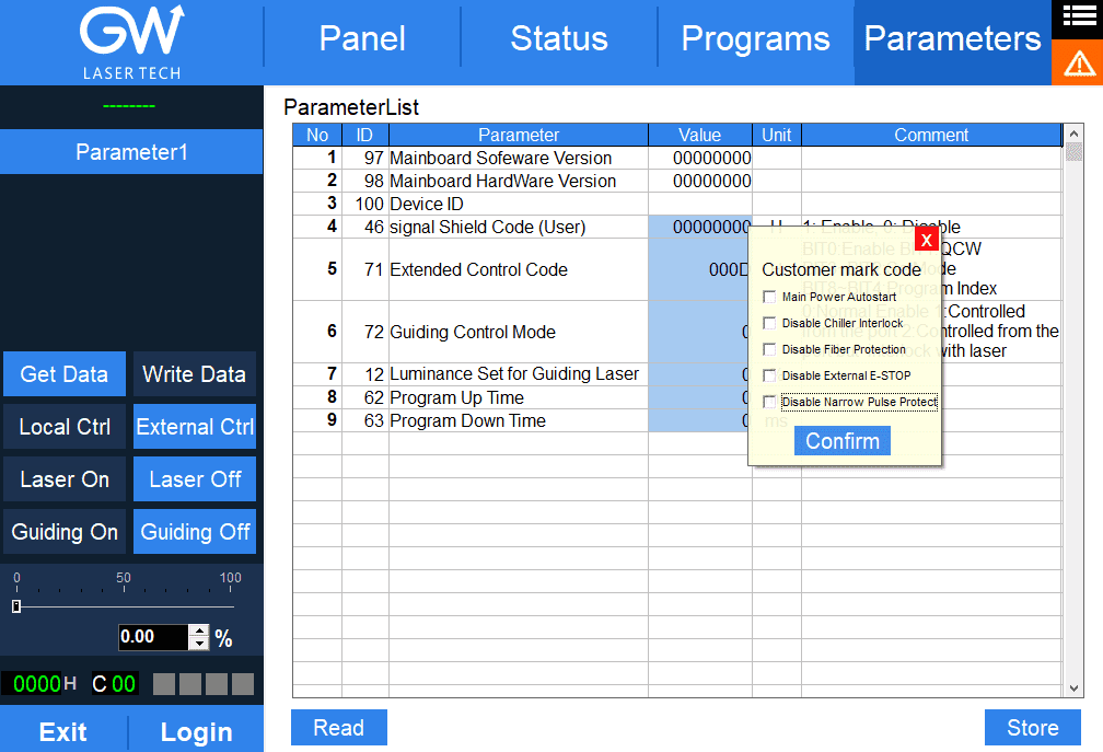
User-Level Signal Mask Code
In row 4, "Signal Mask Code (User Level)", right-click the value field and check the alarm items you wish to mask — the corresponding alarms will then be masked.
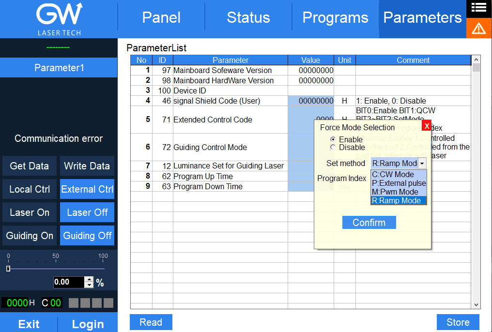
Extended Control Code Configuration
In row 5, "Extended Control Code", right-click the value field and set "Force Mode Selection" to Enabled. Choose the desired mode, click "Confirm" and then "Store" — the basic laser setup is now complete.
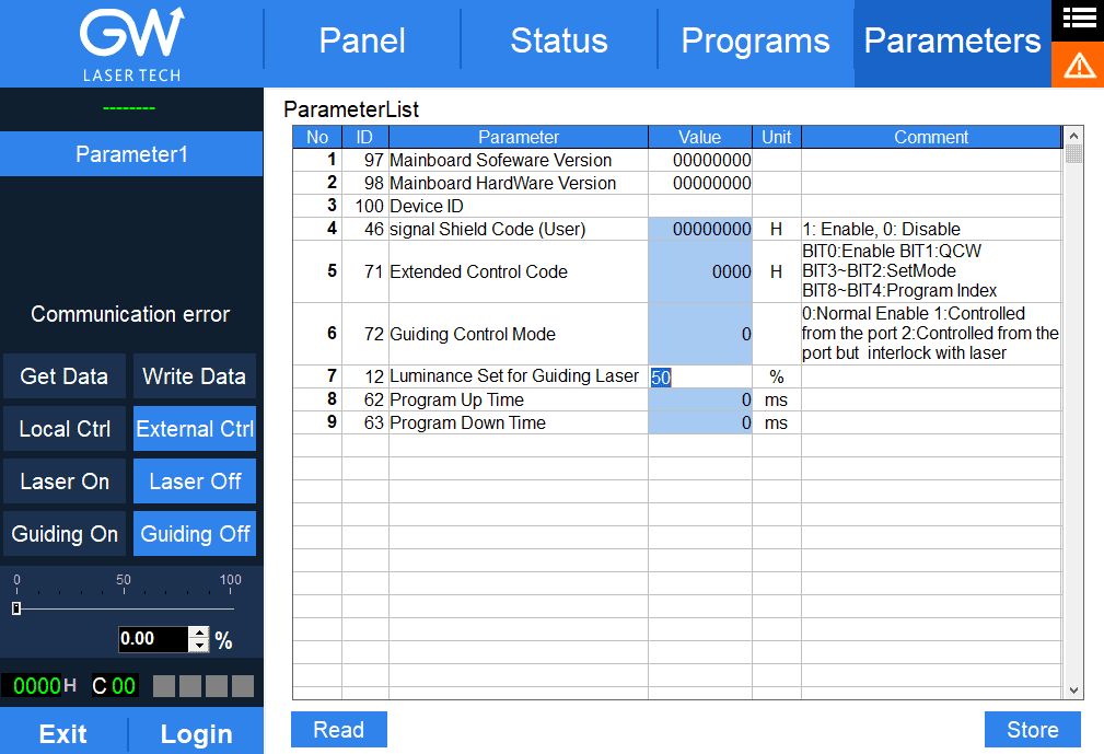
Pilot Laser Brightness Adjustment
If the pilot beam appears too dim, increase the "Luminance Set for guiding Laser" value. Press Enter after the change, then click "Store" to complete the setting.
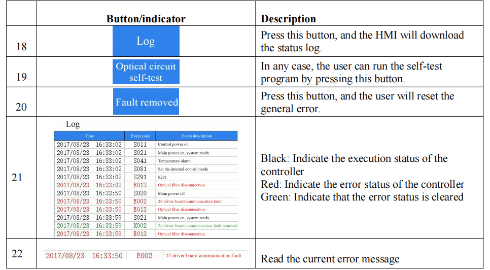
Viewing Current Alarms
Click the Warning icon in the upper-right corner, then click "Interface Log". The "Current Fault List" will display the active alarms.
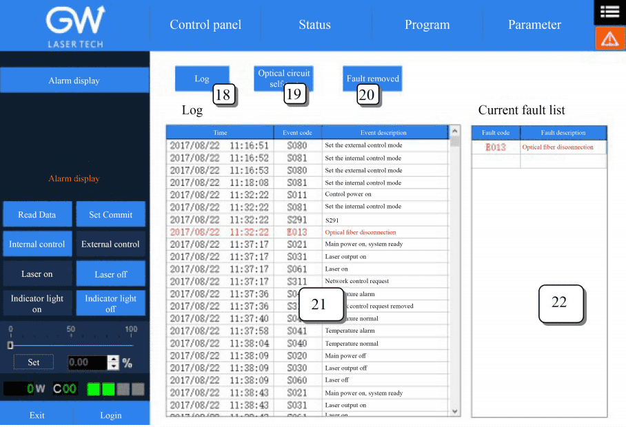
Querying History Records
Click "Log" to retrieve historical records.
PART 03
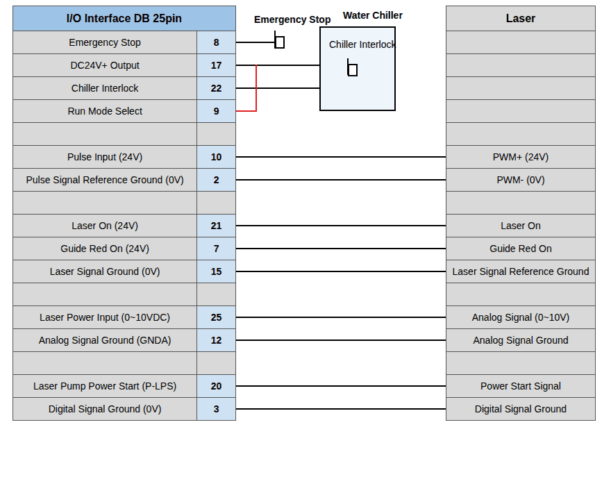
Wiring Definitions (I/O Interface, DB 25-pin)
Below is the wiring definition diagram of the device's I/O interface (DB 25-pin). Refer to it when making field connections.
PART 04
Common Alarms & Solutions
When an alarm occurs on site, please troubleshoot item by item according to the table below.
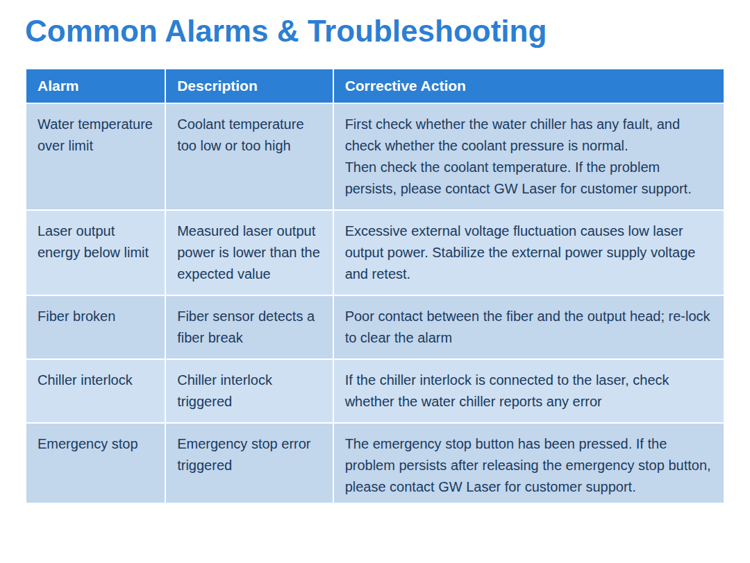
Water Temperature Out of Range
Description: The coolant temperature is too low or too high.
Solution: First check whether the water chiller is malfunctioning and whether the coolant pressure is normal; then check the coolant temperature. If the problem persists, please contact GW Laser for customer support.
Laser Output Energy Below Lower Limit
Description: The measured laser output power is lower than the expected value.
Solution: Excessive external voltage fluctuations may cause low laser output power. Check and stabilize the external supply voltage, then retest.
Fiber Disconnected
Description: The fiber sensor has detected a fiber break.
Solution: The fiber is not properly seated against the output head. Retighten the connection to clear the alarm.
Chiller Interlock
Description: The water chiller interlock has been triggered.
Solution: If the chiller interlock is connected to the laser, check whether the water chiller reports any error messages.
Emergency Stop
Description: An emergency stop error has been triggered.
Solution: Release the emergency stop button. If the problem persists after releasing it, please contact GW Laser for customer support.
📌 We recommend saving / forwarding this article to your front-line colleagues. If none of the above methods resolve the issue, please contact the GW Laser After-Sales Team — we are always at your service.
- Follow us

 0